How To Use Rotary Potentiometers In The Circuits Of Electronic Circuits

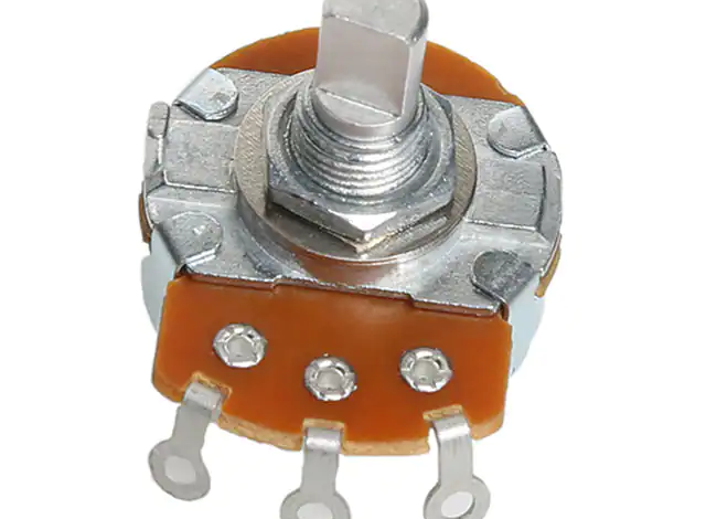
Rotary Potentiometers are a very common component in electronic circuits. They are used to change the resistance of a circuit. In this blog post we will talk about how to use Rotary Potentiometers in Electronic Circuits.
How to Use a Rotary Potentiometer
Rotary potentiometers are used to measure small voltage changes. They are often used in electronic circuits as input devices, such as buttons and dials, to control the power supplied to an electronic device.
To use a rotary potentiometer in a circuit, first determine the output voltage that you need. Next, connect the middle lead of the potentiometer to one side of the circuit’s output voltage supply, and connect the outer leads of the potentiometer to ground. Turn the potentiometer clockwise until you reach your desired output voltage.
Applications of a Rotary Potentiometer
A rotary potentiometer is a common and versatile tool used in electronic circuits. It can be used to adjust the voltage or current levels of an electronic circuit. In this article, we will discuss some applications of a rotary potentiometer in electronic circuits.
A rotary potentiometer can be used to measure the voltage or current levels of an electronic circuit. This is useful when you need to troubleshoot or test an electronic circuit. By measuring the voltage or current level, you can determine whether the circuit is working properly.
Another application of a rotary potentiometer is to create a proportional control system. This type of control system allows you to adjust the output of your circuit in response to changes in input.
Conclusion
GFOOKIC rotary potentiometers are an important part of electronic circuits and can be used in a variety of ways. By understanding how GFOOKIC rotary potentiometers work and using them in the correct way, you can create reliable circuits that function correctly time after time.


